Injection Molding Cooling System Design: Uniform Cooling for Stable Parts

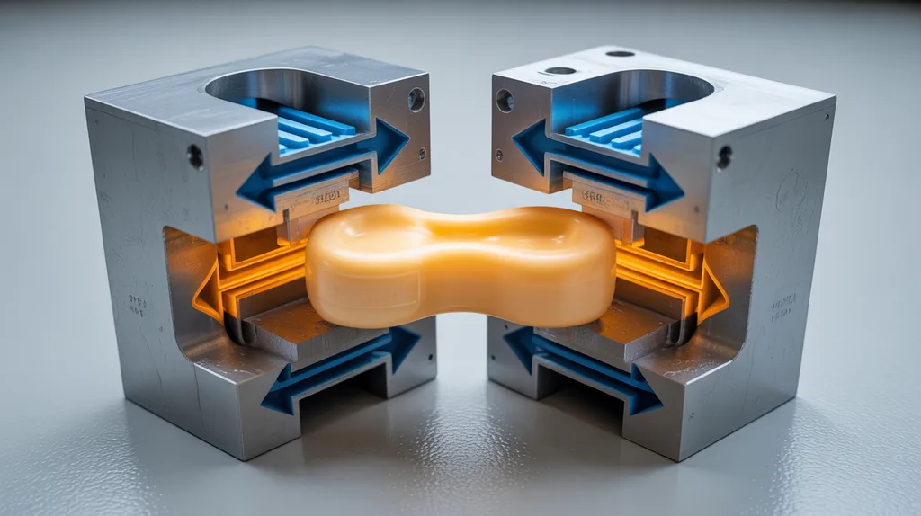
Table of Contents

- Key Takeaways
- What Is an Injection Molding Cooling System?
- Why Uniform Cooling Matters in Injection Molding
- Design Inputs to Review Before Layout
- Core Injection Molding Cooling Channel Design Principles
- Cooling System Configurations and Cooling Features
- Series vs. Parallel Cooling Circuits
- How to Validate an Injection Mold Cooling System Design
- Cooling-Related Defects and Troubleshooting
- Cooling System Maintenance for Stable Production
- Injection Molding Cooling System Design Review Checklist
- When to Use Engineering Support for Cooling Design
- Frequently Asked Questions
- What is an injection molding cooling system?
- What are the main types of cooling systems used in injection molding?
- How do cooling channels affect warpage?
- What is the difference between series and parallel cooling circuits?
- When should conformal cooling be used?
- How do you validate a mold cooling design?


Injection molding cooling system design determines how evenly heat leaves the mold and molded part. A well-designed system places cooling where heat concentrates, balances coolant flow, and accounts for geometry, material, mold construction, and production conditions. The objective is not simply a colder mold, but uniform cooling that helps limit warpage, shrinkage, dimensional drift, and unnecessary cycle time.
Key Takeaways
- Uniform cooling is more important than simply lowering the mold temperature.
- Cooling-channel layouts should follow part geometry, wall-thickness changes, and expected hot spots.
- Thick sections may require targeted features such as baffles, bubblers, thermal pins, inserts, or conformal channels.
- Series and parallel circuits create different flow-balance and temperature-control considerations.
- Channel proximity must be balanced against mold strength, sealing, drilling access, and manufacturability.
- Cooling designs should be verified through simulation, flow and temperature checks, mold trials, and part inspection.
- Cooling is only one possible cause of warpage, sink marks, and dimensional variation; packing, material, gate location, and part geometry must also be reviewed.
What Is an Injection Molding Cooling System?
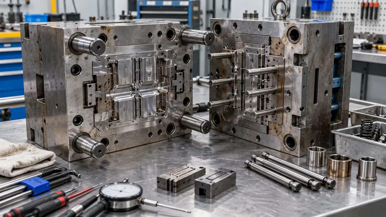
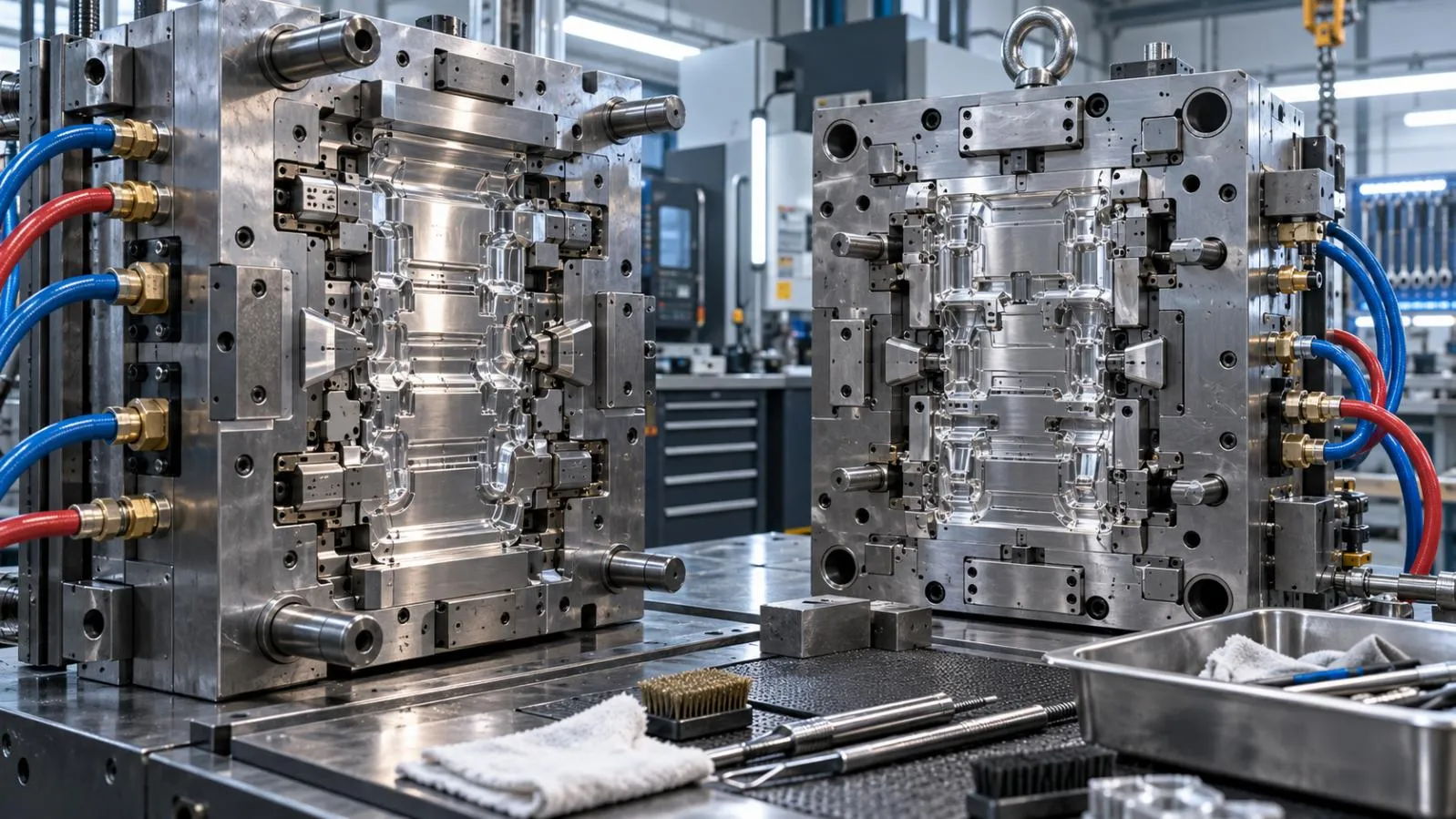
An injection molding cooling system is the network of channels, circuits, fittings, manifolds, and temperature-control equipment used to remove heat from the mold and molded part.
During molding, hot polymer enters the cavity and transfers heat into the cavity and core surfaces. Coolant flowing through the mold carries that heat away. The system may include:
- Straight-drilled cooling channels
- Conformal cooling channels
- Separate cavity and core circuits
- Baffles and bubblers for difficult-to-reach areas
- Thermal pins or cooling inserts
- Coolant manifolds, hoses, and fittings
- Temperature-control units and monitoring points
The system controls both mold temperature and the rate at which the part can be cooled before ejection. However, cooling design is not simply a matter of making the mold as cold as possible. Excessive or uneven cooling can create temperature gradients, differential shrinkage, and dimensional instability.
Cooling should therefore be considered alongside the broader Design Considerations for Precision Injection-Molded Components, including wall thickness, part geometry, draft, ejection, gates, and mold construction.
[DIAGRAM: Cross-sectional injection mold showing the cavity, core, molded part, cooling channels, coolant inlet, coolant outlet, and direction of heat transfer.]
Why Uniform Cooling Matters in Injection Molding
Cooling and cycle time
Cooling is often a major part of the molding cycle because the polymer must become sufficiently stable for ejection. If the mold or part remains hot, the cycle may need to be extended to prevent deformation.
Reducing cooling time can improve productivity, but a shorter cycle is not automatically better. If the cooling system creates large temperature differences across the part, the result may be:
- Warpage after ejection
- Inconsistent dimensions
- Sink marks in thick areas
- Ejection damage
- Part-to-part variation
The practical goal is an appropriate and repeatable cooling cycle, not the lowest possible cooling temperature or shortest theoretical time.
Cooling and part quality
When one region of a part cools faster than another, the regions may shrink at different rates. This can produce deformation, uneven surfaces, or dimensions that change after ejection.
Cooling-related quality problems can include:
- Warpage and twisting
- Differential shrinkage
- Sink marks
- Uneven surface appearance
- Dimensional drift
- Difficult ejection
- Variation between cavities
Cooling is not the sole cause of these problems. Packing pressure, hold time, gate position, resin behavior, wall-thickness variation, venting, and mold temperature settings may also contribute.
Cooling and dimensional stability
Uniform cooling helps different regions of the part reach a stable condition more consistently. This is particularly important for parts with large flat surfaces, tight dimensional requirements, thick bosses, ribs, deep cores, or significant changes in wall thickness.
For critical parts, cooling performance should be assessed together with the applicable tolerances standards, rather than evaluated only through visual appearance.
Design Inputs to Review Before Layout
A cooling system should be designed from the part and tooling requirements outward. Placing channels before reviewing the geometry can leave hot spots that are difficult or impossible to correct later.
Part geometry and wall-thickness distribution
Begin by mapping the areas most likely to retain heat:
- Thick walls
- Bosses and ribs
- Deep cores
- Long sections with limited mold access
- Inserts and metal components
- Slides and lifters
- Regions near the gate or weld lines
Thick sections generally require more time to cool than thin walls. A visually simple part may still need a carefully zoned cooling layout if it contains localized mass or difficult-to-reach features.
Polymer and material behavior
The selected polymer affects the thermal load, processing temperature, shrinkage behavior, and sensitivity to temperature differences. Resin data and the intended processing window should be considered during cooling design.
The cooling system must also work with the mold material, insert material, surface requirements, and production process. A general cooling layout cannot be transferred unchanged from one polymer or part geometry to another.
Mold construction and tool material
Review the complete tool structure before locating channels. Important constraints include:
- Cavity and core dimensions
- Parting lines
- Slides and lifters
- Ejector pins and return systems
- Inserts
- Fasteners
- Sealing surfaces
- Drilling and plugging access
- Structural steel thickness
Cooling channels must remove heat without weakening the mold or creating leak paths. Tool material and insert selection also influence heat transfer and should be treated as project-specific engineering decisions.
Production requirements
The design review should include:
- Expected cycle time
- Production volume
- Dimensional requirements
- Cosmetic requirements
- Number of cavities
- Available temperature-control equipment
- Monitoring and maintenance procedures
- Required trial and inspection conditions
For parts with complex features or strict dimensional requirements, cooling design should be reviewed as part of the overall DFM for injection molding process.
Core Injection Molding Cooling Channel Design Principles
Place cooling near heat-concentrated areas
Channels should be positioned to remove heat from the regions that need it most, especially thick sections, deep cores, bosses, and inserts.
However, “closer” does not automatically mean “better.” The channel must remain far enough from the cavity surface and other features to preserve:
- Mold strength
- Sealing integrity
- Drilling access
- Tool life
- Machining feasibility
- Resistance to leakage
The appropriate distance, channel size, and layout depend on the mold material, geometry, coolant, pressure, and manufacturing method. Avoid applying a universal spacing rule without checking the actual tool design.
Use consistent, manufacturable channel geometry where appropriate
Consistent channel geometry can make flow behavior and manufacturing easier to control. It may also simplify inspection, plugging, cleaning, and maintenance.
Nevertheless, all channel sections do not necessarily need to be identical. Local features, restricted access, pressure loss, and heat concentration may justify changes in routing or cooling method. Any change should be evaluated for its effect on flow balance and serviceability.
Cool both mold halves where necessary
The cavity and core should be reviewed as a complete thermal system. Both sides may contribute significantly to heat removal, although the thermal load and geometry may not be identical.
A layout that cools one mold half effectively while neglecting the other can leave a temperature imbalance across the molded part. Cooling zones should therefore be designed around actual heat flow rather than simply mirrored for appearance.
Design for balanced coolant flow
A channel drawing may look balanced while still producing unequal flow. Flow depends on factors such as:
- Circuit length
- Channel restrictions
- Branch resistance
- Pressure drop
- Manifold arrangement
- Fittings and connectors
- Coolant temperature and properties
- Blockages or contamination
Parallel branches require particular attention because coolant may favor the path with lower resistance. Circuit balance should be supported by calculations, simulation, flow checks, or trial measurements rather than assumed from the CAD layout alone.
Account for mold strength and serviceability
Cooling channels must avoid critical structural areas, ejector systems, slides, inserts, and sealing surfaces. The layout should also allow technicians to:
- Connect hoses and fittings
- Test for leaks
- Clean the circuits
- Remove plugs where appropriate
- Inspect for blockage
- Repair or replace service components
A channel that performs well in a new mold but cannot be maintained efficiently may create production problems later.
Cooling System Configurations and Cooling Features
Straight-drilled cooling channels
Straight-drilled channels are widely used where the mold geometry and drilling access allow practical routing.
Potential strengths include:
- Familiar manufacturing methods
- Straightforward inspection
- Relatively simple plugging and sealing
- Practical maintenance access
- Compatibility with many conventional mold layouts
Their main limitation is routing flexibility. Straight channels may not follow curved surfaces or reach deep, irregular, or isolated hot spots effectively.
Conformal cooling channels
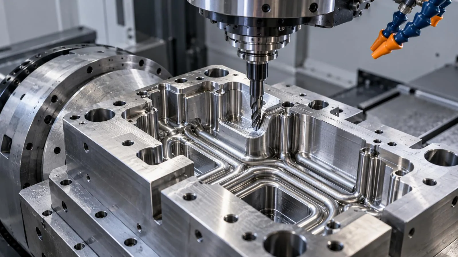
Conformal cooling channels follow the cavity or core geometry more closely than conventional drilled channels. They may be considered when complex geometry or localized heat concentration makes straight-drilled cooling inadequate.
Potential applications include:
- Deep cores
- Complex curved surfaces
- Thick areas surrounded by thin walls
- Difficult-to-cool inserts
- Parts where temperature uniformity is especially important
Conformal cooling is not automatically a better solution. The design must also consider manufacturing method, cost, inspection, repair, sealing, and long-term maintenance. It is most appropriate when the expected thermal benefit justifies the added tooling complexity.
Baffles
Baffles redirect coolant into narrow or difficult-to-reach areas. They can help extend the effective cooling path where a straight channel cannot reach the required region directly.
A baffle design should be checked for:
- Flow direction
- Pressure loss
- Sealing
- Installation access
- Risk of blockage
- Maintenance requirements
Bubblers
Bubblers are commonly used in deep or slender cores. Coolant travels through an internal tube or feature and returns through the surrounding passage, allowing cooling to reach areas that would otherwise remain hot.
The bubbler’s dimensions, return path, flow resistance, and sealing arrangement must be compatible with the core and the intended production conditions.
Thermal pins and cooling inserts
Thermal pins and cooling inserts can provide localized heat transfer in areas where conventional channels are difficult to place. They may be useful around deep features, isolated hot spots, or inserts.
Their effectiveness depends on the surrounding mold structure, contact conditions, material selection, geometry, and ability to transfer heat into the main cooling system.
Series vs. Parallel Cooling Circuits
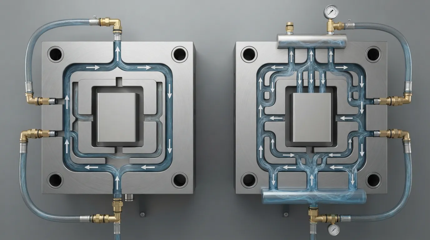
The choice between series and parallel circuits should be based on geometry, heat load, flow behavior, and monitoring requirements.
| Circuit approach | Potential strengths | Design risks or limitations | Review points |
|---|---|---|---|
| Series circuit | Simple routing and fewer branches in suitable layouts | Coolant temperature may change along the circuit; downstream areas may receive warmer coolant | Total path length, temperature rise, pressure drop |
| Parallel circuit | Can supply separate regions more directly | Unequal branch resistance may create uneven flow | Manifold design, branch balance, flow measurement |
| Mixed circuit | Can adapt to complex cavity and core layouts | Greater design and validation complexity | Zone separation, balancing, monitoring, maintenance |
In a series circuit, the coolant passes through one section before reaching the next. This can simplify routing, but the coolant temperature and pressure conditions may vary along the path.
In a parallel circuit, flow divides among branches. This can provide more direct cooling to separate zones, but branches must be designed so that one path does not receive substantially more flow than another.
The correct choice depends on the tool. Circuit design should be evaluated as a flow network, not only as a two-dimensional channel drawing.
How to Validate an Injection Mold Cooling System Design
Cooling simulation and thermal analysis
Simulation can help identify:
- Local hot spots
- Temperature gradients
- Cooling-time differences
- Poorly placed channels
- Uneven flow conditions
- Potential improvements to circuit routing
Simulation is a design-validation tool, not a guarantee of production performance. Its usefulness depends on the accuracy of the geometry, material data, boundary conditions, and assumptions.
Cooling review should be integrated into the broader mold design development process before the tool is released for manufacture.
Flow and temperature checks
During commissioning and trials, review the actual cooling behavior rather than relying only on design documentation. Useful checks may include:
- Coolant inlet temperature
- Coolant outlet temperature
- Flow through each circuit or zone
- Pressure behavior
- Leakage and sealing
- Temperature differences between cavity and core regions
- Stability after the mold reaches operating conditions
These checks help identify restrictions, poor circuit balance, blocked passages, and unexpected thermal behavior.
Mold-trial validation
The mold should be allowed to reach stable operating conditions before judging cooling performance. Review:
- Cycle time
- Mold-surface temperature
- Ejection behavior
- Part appearance
- Part deformation
- Cavity-to-cavity consistency
- Process repeatability
A single acceptable part does not necessarily demonstrate long-term production stability. Trial results should be evaluated over enough cycles to identify drift and warm-up effects.
Part inspection
Cooling performance should ultimately be assessed through the molded part. Depending on the application, inspection may include:
- Critical dimensions
- Flatness and warpage
- Sink marks
- Surface appearance
- Part weight
- Ejection marks
- Repeatability between cavities and cycles
Cooling-Related Defects and Troubleshooting
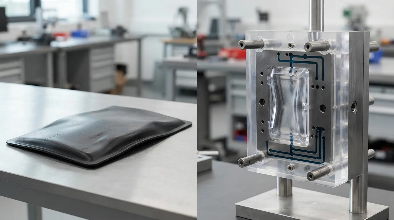
Cooling is one possible cause of molding defects, not an automatic explanation for every problem.
| Symptom | Cooling-related checks | Other possible contributors |
|---|---|---|
| Warpage | Temperature distribution, blocked circuits, cavity/core balance, local hot spots | Packing, gate position, wall thickness, material shrinkage |
| Sink marks | Cooling near thick sections, local heat removal, cycle stability | Packing pressure, hold time, rib or boss geometry |
| Dimensional drift | Coolant temperature, flow loss, mold warm-up, circuit balance | Material moisture, process settings, machine variation |
| Long cooling time | Heat concentration, poor channel access, low flow, fouling | Part thickness, polymer processing window, ejection constraints |
| Uneven surface appearance | Surface-temperature variation, local cooling imbalance | Venting, filling pattern, mold finish, material behavior |
A practical troubleshooting sequence is:
- Confirm coolant flow through each relevant circuit.
- Check inlet and outlet temperatures.
- Inspect for blockage, leaks, fouling, or damaged fittings.
- Compare cavity and core temperatures.
- Review part geometry and process conditions.
- Revalidate the part after corrective action.
Changes to packing, gate design, material drying, or processing conditions may be necessary even when a cooling imbalance is present.
Cooling System Maintenance for Stable Production
A cooling design can lose performance over time if the channels or connections are not maintained. Common problems include:
- Scale and mineral deposits
- Corrosion
- Contamination
- Blocked passages
- Leaking fittings
- Damaged baffles or bubblers
- Reduced flow
- Poor coolant condition
Maintenance should include appropriate inspection of hoses, fittings, seals, flow, and temperature behavior. A gradual increase in cycle time or a change in part dimensions may indicate a cooling problem rather than a sudden machine failure.
Accessible circuits are easier to clean, inspect, and repair. Maintenance planning should therefore begin during mold design. See mold maintenance for related tooling-care considerations.
Injection Molding Cooling System Design Review Checklist
Part review
- [ ] Thick sections and likely hot spots are identified.
- [ ] Ribs, bosses, inserts, deep cores, slides, and lifters are mapped.
- [ ] Dimensional and cosmetic requirements are recorded.
- [ ] Polymer thermal and shrinkage behavior has been considered.
Channel layout
- [ ] Cooling reaches both cavity and core regions where necessary.
- [ ] Channel locations preserve mold strength.
- [ ] Drilling, plugging, sealing, and inspection are feasible.
- [ ] Difficult areas have an appropriate local cooling solution.
- [ ] The design avoids ejector systems, fasteners, slides, and critical sealing surfaces.
Circuit design
- [ ] Series, parallel, or mixed routing has been justified.
- [ ] Flow paths are clearly zoned.
- [ ] Branch resistance and pressure drop have been considered.
- [ ] Inlet and outlet temperatures can be checked.
- [ ] Flow balance can be verified during trials.
Validation
- [ ] Simulation or thermal review has been completed where appropriate.
- [ ] Flow and temperature checks are planned.
- [ ] Leakage and sealing checks are defined.
- [ ] Mold-trial conditions are documented.
- [ ] Part inspection criteria are established.
Maintenance
- [ ] Cooling channels and fittings are accessible.
- [ ] Cleaning and blockage checks are practical.
- [ ] Baffles, bubblers, and inserts can be serviced.
- [ ] Cooling-system records can be maintained.
When to Use Engineering Support for Cooling Design
Additional engineering review is especially useful for:
- Complex or thick-walled parts
- Large flat surfaces with strict flatness requirements
- Deep cores and isolated hot spots
- Multiple-cavity tools
- Parts with demanding cosmetic requirements
- Persistent warpage or sink marks
- Cooling layouts that are difficult to manufacture or maintain
- Designs where cycle time and dimensional stability are both critical
Cooling design should be coordinated with part design, DFM, mold construction, simulation, toolmaking, trial molding, and inspection. A relevant example of cooling hardware can be reviewed through the stainless steel mold cooling module, but any example should be evaluated in the context of its specific geometry and application.
Frequently Asked Questions
What is an injection molding cooling system?
An injection molding cooling system is the network of channels, circuits, coolant connections, and auxiliary features that removes heat from the mold and molded part. Its design affects temperature uniformity, cycle time, and part stability.
What are the main types of cooling systems used in injection molding?
Common approaches include straight-drilled cooling channels, conformal cooling channels, and localized features such as baffles, bubblers, and thermal pins. The suitable option depends on part geometry, heat concentration, manufacturability, and validation requirements.
How do cooling channels affect warpage?
Uneven heat removal can create temperature gradients and differential shrinkage across the part. Cooling is one possible contributor to warpage; packing, gate position, wall thickness, material shrinkage, and part geometry must also be reviewed.
What is the difference between series and parallel cooling circuits?
Series circuits route coolant through connected sections, while parallel circuits divide flow among branches. Series layouts may experience coolant temperature rise along the path. Parallel layouts require careful branch balancing to distribute flow consistently.
When should conformal cooling be used?
Conformal cooling may be considered when complex geometry, deep cores, or localized hot spots make conventional channels ineffective and the added manufacturing, cost, repair, and validation requirements are justified.
How do you validate a mold cooling design?
Validation may combine cooling simulation, flow and temperature checks, leakage inspection, mold trials, cycle stabilization, and dimensional and visual inspection of molded parts. No single check is sufficient for every tool.
Uniform cooling is the result of coordinated design rather than one universal channel layout. When geometry, heat load, circuit balance, manufacturability, validation, and maintenance are considered together, the cooling system is more likely to support stable parts and repeatable production.
- PREV: Null
- NEXT: Null

Yijiang is a professional custom manufacturing partner specializing in large-scale injection molding and precision mold development. We support global clients in automotive,
in large-scale injection molding and precision mold development. We support global clients in automotive,


Get a quote from the China’s #1 CNC Machining Services.
Ready to get started? Connect with us today!
 Talk to Our Team