Home » Two-Shot Mold Design for High-Precision Parts: Gate Location, Shrinkage, and Cooling Strategies
Two-Shot Mold Design for High-Precision Parts: Gate Location, Shrinkage, and Cooling Strategies

Table of Contents

- 1. Establish Dimensional Control Before Finalizing the Mold Structure
- 2. Gate Location: Balance Packing Pressure and Substrate Stability
- 3. Differential Shrinkage: Consider Two Materials and Two Thermal Histories
- 4. Cooling Strategy: Eliminate Warpage While Preserving Bonding
- 5. Demonstrate/Evaluate Dimensional Stability Over the Entirety of the Molding Process


A rigid plastic housing may meet its dimensional tolerances after the first shot but warp after the second. While some problems are caused by the machining of the cavities, the pressure of the second shot can deflect the substrate and locally reheat it. As the injection molded plastic cools and contracts, it can distort even further, thus dimensional tolerance can be lost.
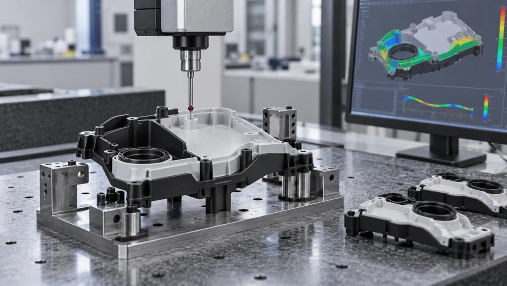
Factors such as the location of the gate, the position of the substrate, shrinkage and the removal of heat have to be considered to produce a high-precision component using Two-Shot Mold Design. If, for example, the design changes to move a defect, it may simply be relocated.
1. Establish Dimensional Control Before Finalizing the Mold Structure
The first engineering decision is identifying which dimensions must remain stable after both materials have cooled.
A mounting boss, for example, may require tight positional accuracy relative to a sealing surface. If the second-shot cavity applies pressure to an unsupported wall, the boss can shift even when the first-shot dimensions are correct.
The mold layout must work within these restrictions:
- Some critical locating surfaces need to be supported during the second injection to prevent deformation.
- For mechanisms such as rotary and indexing, there must not be a large clearance that causes misalignment.
- The last contact between the first shot cavity and the steel must prevent flash. This contact should not crush or mar the first shot part.
A rotary mold provides better repeatability for locating parts for indexing or rotary mechanisms. Core-back molds also eliminate handling between injections.
Neither type of mold guarantees better dimensional accuracy. Which type of mold is chosen depends on the location of the functional tolerances. Other factors such as the part and machine geometry and the volume of the part also affects the mold choice.
One frequently overlooked detail is substrate temperature at the second-shot stage. A first-shot component may still be substantially warmer than its final inspection condition. Designing the secondary cavity around room-temperature dimensions can produce unexpected interference, flash, or substrate deformation.
2. Gate Location: Balance Packing Pressure and Substrate Stability
Gate placement affects more than filling time. It determines how pressure propagates through the melt, where flow fronts meet, and how molecular orientation develops.
First-Shot Gate Position and Packing
For a rigid structural substrate, the first gate should provide an effective packing path to thick sections and critical features.
A gate positioned too far from a mounting boss may allow the connecting flow section to freeze before sufficient packing pressure reaches the boss. The resulting local contraction can produce sink marks, ovality, or positional errors.
Moving the gate closer can improve pressure transmission, but may introduce excessive local orientation, gate vestige, or a weld line elsewhere.
Gate thickness and runner pressure loss must be evaluated together. Increasing holding pressure cannot compensate for insufficient packing once the gate has frozen.
A practical verification method is to examine first-shot part mass over increasing holding times, alongside cavity-pressure data where available. A mass plateau can help identify effective gate freeze-off, although dimensional measurements are still necessary to confirm adequate packing.
Second-Shot Gate Position and Melt Impact
The second injection introduces a different failure mechanism: melt pressure acts directly on an already molded substrate.
When the gate directs flow toward an unsupported thin wall, local pressure can deflect the wall and change the secondary cavity thickness. Once the material solidifies, the deformation may remain locked into the finished component.
Gate positioning should therefore consider:
• The direction of melt flow relative to substrate support.
• Pressure loading near shut-off edges, where excessive force may cause flash.
• Flow-front convergence near sealing lips or mechanically stressed interfaces.
A balanced filling pattern is not necessarily the pattern with the shortest flow length. For precision overmolded features, substrate stability may be more important than minimizing injection pressure alone.
3. Differential Shrinkage: Consider Two Materials and Two Thermal Histories
Allowances for shrinkage become less reliable when two different polymers are molded in sequence.
In a multiple shot process, the first shot plastic has partially cooled and contracted and receives a second melting. Reheating in the second shot can create thermal gradients and redistribute residual stress.
Three Types of distortion can occur to the part.
• Volumetric shrinkage can be unequal. PVT (pressure-volume-temperature) behavior can be different for different polymers. The effects of mold shrinkage cannot fully describe the contracted state of a rigid substrate and an elastomer overmold.
• Flow-induced shrinkage anisotropy can occur with polymers containing fibers. Gate location can affect warpage.
• Shrinkage can also be constricted. A restrained dimension cannot fully relax, resulting in the bonded materials trying to shrink to a different size, which can lead to delamination and edge lifting.
For a PC/ABS housing with a TPE seal, final part geometry can be impacted by the degree of shrinkage of the PC/ABS and the TPE.
Bonding must also be evaluated using the actual commercial grades. A nominal PC/ABS–TPE pairing does not establish adhesion compatibility.
During mold development, simulation should use available grade-specific thermal and rheological data. When complete material characterization is unavailable, predicted warpage should be treated as a comparative design indicator rather than a guaranteed dimensional result.
4. Cooling Strategy: Eliminate Warpage While Preserving Bonding
In two-shot mold design, cooling time and temperature distribution affect the rigidity of the substrate and the bond between the two layers.
Rigidity of the first shot can be affected if the mold is cooled too quickly, thus, causing the surface of the first shot to be cooled to a temperature that is too low to allow bonding with the second shot. If the first shot is not cooled enough, it may be deformed by the second shot.
The balance required to prevent these consequences depends on the kind of adhesion the interface relies on, for example, molecular adhesion or mechanical interlocking.
Account for Localized Temperature Differences
Differential contraction may occur if a section of the mold that contains cooling channels (used to cool the mold) becomes too cool and contracts more than other parts of the mold. This may cause functional surfaces of the mold to become distorted.
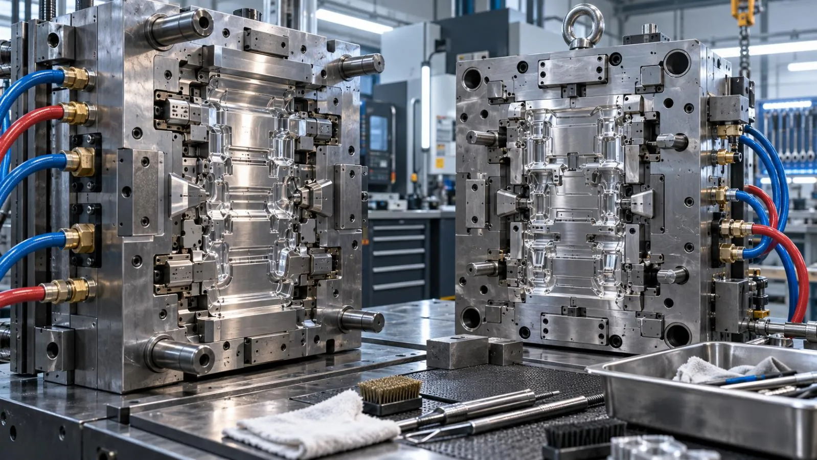
Factors that should be analyzed in the design of cooling circuits include:
• How close the cooling channels are to thick sections of the mold.
• Differences in temperatures of the cooling fluids in the various circuits.
• Differences in temperatures of the surfaces of the mold.
• Accumulation of heat in and around obstructions in the flow of the cooling fluid.
Uniformity of cooling should not be confused with the need to maintain identical temperatures on both surfaces of the mold. This may not always be the case, for example, if the first material is cooled sufficiently and bonding is required between the first and the second materials, the second material may not be allowed to be bonded to the first material at a temperature that is too low.
It may be more cost-effective to make adjustments to the cooling system to account for warpage caused by other factors such as an improperly positioned gate.
5. Demonstrate/Evaluate Dimensional Stability Over the Entirety of the Molding Process
Simulation techniques can assist in designing gate locations, packing profiles, and molding thermal balancing. Actual processing trials are required to confirm operation within defined process windows.
Distinguishing first shot from subsequent shot defects is essential for any effective validation method.
Prior to secondary processing, verify locating features and critical dimensions. Flatness of the substrate should also be verified and the temperature and time of the transfer should be documented.
After the first shot is taken, dimensions of the part should be evaluated to ensure the features of the molded interface are correct. Flash and other mold defects should also be evaluated.
Various experiments should be performed to fully understand the effects of parameters on the molded parts. However, to achieve control of a process, it is often necessary to vary one or more input parameters.
One of the last steps is to perform a peel test to check adhesion of the part and to ensure it is leak-tight and a thermal cycle test to check the part for cracks or other flaws.
Molded parts are still in a temporarily fixed state. Measurements taken by the mold maker or a third party immediately after ejection from the mold may not represent dimensions of a part at equilibrium.
Industrial consumers should require the qualification of manufacturing processes to include realization of specified material grades, tolerances, and the resolution of manufacturing risks.
Tooling Development with Yijiang Technology
Yijiang Technology is capable of CAD and CAE analysis of mold flows, CNC and EDM services, injection and composite molding, and overmolding.
We can assess tooling and machine shop feasibility to produce multi-material and two-shot injection molded components. The availability of a specific two shot machine to produce a given component should be confirmed during the assessment.
Contact Yijiang Technology to review your design and manufacturing requirements.
FAQs
Q1. Does Yijiang Technology provide mold design for high-precision plastic parts?
Yes. Yijiang Technology provides custom injection mold design, tooling development, and precision mold manufacturing for industrial applications.
Q2. Can Yijiang Technology evaluate gate locations before mold manufacturing?
Yijiang uses CAE mold-flow simulation during mold development. The scope of gate-location analysis should be confirmed for each project.
Q3. How does Yijiang Technology address shrinkage and warpage risks?
Its engineering workflow includes mold-flow analysis, tooling development, and trial molding. Final dimensional performance requires physical validation.
Q4. Can Yijiang Technology support cooling-system design for precision molds?
Cooling requirements can be considered during mold development. Project-specific cooling simulation and thermal validation should be confirmed with its engineering team.
Q5. Does Yijiang Technology manufacture precision mold components?
Yes. Yijiang uses CNC machining and EDM for mold cavities, cores, and complex tooling components.
- PREV: Null
- NEXT: Null

Yijiang is a professional custom manufacturing partner specializing in large-scale injection molding and precision mold development. We support global clients in automotive,
in large-scale injection molding and precision mold development. We support global clients in automotive,


Get a quote from the China’s #1 CNC Machining Services.
Ready to get started? Connect with us today!
 Talk to Our Team