


 Home »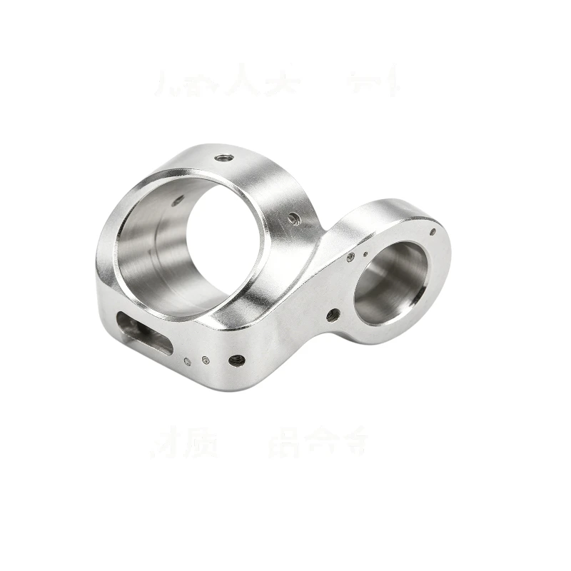


Aluminum Robot Joint Housing
This aluminum robot joint housing is a precision structural enclosure designed for collaborative robots, industrial robotic arms and automated handling equipment. Monolithically shaped from high-strength lightweight aviation aluminum alloy, the component features dual bearing chambers, distributed mounting holes and positioning slots integrated in one piece. Manufactured via five-axis simultaneous machining, it achieves ultra-precise bore concentricity and smooth complex curved outlines, offering stable structural protection, accurate bearing positioning and consistent assembly benchmarks for robot joint drive modules. It fully satisfies industrial robot standards for light weight, high rigidity and repeat positioning accuracy under frequent reciprocating movements.
- Machining Process: 5-axis simultaneous CNC milling, drilling, tapping, micro deburring, hard anodizing optional
- Material: Aviation Aluminum Alloy (6061-T6 / 7075-T6 customizable)
- Accuracy: Standard ±0.01 mm, ultra-precision bore tolerance up to ±0.005 mm
- Surface Finish: Bright as-machined finish, hard anodizing (black/silver) optional
- Features: Lightweight, high structural rigidity, excellent bore concentricity, wear-resistant anti-corrosion coating available
 Get Free Quote


Precision Housing for Robotic Joint Drive Systems
The aluminum robot joint housing forms the structural link between bearings, drive components, joint covers and adjacent arm sections. Machined from a single block of high-strength aviation aluminum, it combines two bearing chambers, distributed mounting holes, locating slots and curved exterior surfaces within one continuous component.
The monolithic structure removes joints between separate bearing supports and the outer frame. This helps both bearing seats remain stable under repeated acceleration, deceleration and directional changes. Lower component weight also reduces the moving mass carried by the joint, supporting faster response without placing unnecessary load on motors and reduction drives.
Dual-Bore Concentricity From Five-Axis Machining
The relationship between the two bearing chambers directly affects shaft alignment, gear engagement and joint rotation. Five-axis simultaneous machining reaches the internal bores, angled mounting faces and curved outer profile from several directions while retaining a shared coordinate system.
Fewer reclamping operations reduce positional variation between bearing centers, locating features and fastening points. Boring, circular interpolation and finish milling can control bore diameter, roundness and coaxial relationships according to the assembly specification. Coordinate measurement can verify the spatial position of both chambers and their connection to the primary installation datums.
The same machining cycle can form threaded holes, cable passages, positioning slots and recessed mounting areas. Integrating these details into the housing reduces separate brackets and helps the drive module follow a consistent assembly reference.
Lightweight Rigidity for Repeated Joint Movement
Aviation aluminum provides the stiffness required to hold bearing positions while keeping the housing lighter than a comparable steel structure. Material remains around load paths, bearing walls and fastening zones, while lower-stress regions can use hollow or curved sections to remove excess mass.
The curved exterior also gives the joint housing clearance around rotating arm sections and protective covers. Smooth transitions between thick and thin areas help distribute mechanical stress during frequent reciprocating movement. Optional anodizing can improve surface wear resistance, corrosion protection and appearance without adding substantial weight.
Core Advantages
- Lightweight with Outstanding Structural Rigidity: Premium aviation aluminum material greatly lowers the overall weight of robot joints to ease motor load and cut power consumption, while maintaining enough rigidity to avoid structural deformation during high-speed reciprocating rotation.
- Ultra-High Bore Concentricity from Integrated Machining: Dual bearing chambers are processed in a single five-axis clamping cycle, which eliminates alignment errors from multiple re-clamping. Perfect concentricity prevents bearing and motor shake, improving the robot’s movement smoothness and repeated positioning precision.
- One-Piece Multi-Functional Integrated Outline: Curved outer contours, mounting holes, positioning slots and limit grooves are all formed as a single unit. No extra auxiliary connecting fixtures are required, which streamlines the assembly process of robot joint modules and shortens production cycles.
- Long-Lasting Wear & Corrosion Resistance: Optional hard anodizing treatment elevates the surface hardness significantly, defending the housing against scratches, oxidation, and erosion from workshop cutting fluids during long-term continuous production runs.
- Fully Customizable Structural Design: Inner bore diameters of bearing chambers, distribution layout of mounting holes, overall outer dimensions and positioning slot profiles can all be customized strictly according to your robotic arm engineering drawings.
Common Applications
Final inspection can cover bore diameter, coaxiality, mounting-hole position, profile dimensions and datum relationships. Each aluminum robot joint housing can also undergo trial assembly with bearings or drive components to confirm fit before entering scheduled equipment production.
Specification Table
| Parameter | Details |
| Raw Material | 6061-T6 Aviation Aluminum Alloy; high-strength 7075-T6 aluminum available upon request |
| Machining Process | 5-axis simultaneous CNC milling, drilling, tapping, internal & external micro deburring, optional hard anodizing surface treatment |
| Dimensional Tolerance | Standard ±0.01 mm overall tolerance; custom ultra-precision ±0.005 mm tolerance for bearing inner bores |
| Surface Finish | Standard bright machined metal finish, hard anodized coating (silver / black color optional) |
| Bore Inner Diameter Range | Customized based on robot design drawings, common range: 10 mm – 80 mm |
| Maximum Overall Machining Size | Customized per customer drawings, max processing dimension: 400 mm |
| Continuous Working Temperature | -20℃ ~ +120℃ |
| Quality Control | Full 3D CMM dimensional scanning inspection, bore concentricity runout testing, thread gauge calibration, surface hardness test for anodized workpieces |
Recommended Case Studies


Start Your Project Inquiry
our information is kept confidential and reviewed directly by our engineering team. We typically respond within 1 business day with practical technical feedback.


